Featured

Doing Engineering in South America

This is the post excerpt.

Doing Engineering in South America is a title with a dramatic content. Requires special skills to perform a business that is becoming more difficult every day. It is not a secret that Oil & Gas Industry in developing countries still being a challenging matter for American companies as well as for American managers, engineers, and technicians. Political instability and economic fluctuations still demanding a high-risk ability to absorb the high cost of human resource and economic worth.

Below is a series of publications that have been prepared with the intention of illustrating, from the point of view of an engineer, about the business of making engineering in South America.

howard-refinery-1

ISO Standards for use in the Oil & Gas industry

ISO-008

Summarized by Howard Velasquez, BS.CE., M.ASCE, 

ISO-006These ISO standards, TR and TS (abbreviated titles) are only a core collection of several hundreds of standards available for the oil & gas industry from ABNT, NSI, API, AS, BSI, CSA, NORSOK, NF, GOST, SAC etc. Some ISO/TC67 standards have been withdrawn and the relevant API standard is referenced above.

ISO-007

ISO 10418 Process safety systems (Rev)

ISO 10419 Replaced by API Spec 6AV2

ISO 10423 Wellhead & Christmas tree equipment

ISO 12489 Reliability modeling/safety systems

ISO 13354 Shallow gas diverter equipment

ISO 13533 Drill-through equipment (BOPs)

ISO 13534 Hoisting equipment – care/maintenance

ISO 13535 Hoisting equipment – specification

ISO 13626 Drilling and well-servicing structures

ISO 13702 Control and mitigation of fires and explosions

ISO 13703 Offshore piping systems

ISO 14224 Reliability and maintenance data (Rev)

ISO 14692 GRP piping, Parts 1-4 (Rev)

ISO 14693 Drilling equipment

ISO 15138 Heating, ventilation, and air-conditioning (Rev)

ISO 15156 Cracking-resistant materials for use in H2S environments, Parts 1-3

ISO 15544 Emergency response

ISO 15663 Life cycle costing, Parts 1–3

ISO 16901 Risk assessment in the design of onshore LNG installations

ISO 16903 Characteristics of LNG influencing design and material selection

ISO 16904 LNG Marine Transfer Arms (New)

ISO 17177 Unconventional LNG transfer systems

ISO 17292 Metal ball valves

ISO 17776 Major Accident hazard management during design (Rev)

ISO 17781 Duplex stainless steel materials testing requirements (New)

ISO 17782 Qualification of manufacturers of special materials (New)

ISO 17945 Materials resistant to sulfide stress cracking

ISO 17969 Guidelines on competence for personnel (Rev)

ISO 18683 Systems and installations for supply of LNG as fuel to ships

ISO 19008 Standard Cost Coding System (New)

ISO 20815 Production assurance and reliability management

ISO 21457 Materials selection

ISO 23936-1 Thermoplastics

ISO 23936-2 Elastomers

ISO 27469 Method of test for offshore fire dampers

ISO 29001 Sector-specific quality management systems

ISO 13624 Marine drilling riser systems, Parts 1-2

ISO 13625 Marine drilling riser couplings

ISO 19901-7 Station keeping systems

ISO 10855 Offshore containers, Part 1-3 (New)

ISO 18647 Modular drilling rigs for offshore fixed platforms (New)

ISO 18797-1 Elastomeric coating of risers – polychloroprene or EPDM (New)

ISO 19900 General requirements for offshore structures

ISO 19901-1 Metocean design and operating considerations

ISO 19901-2 Seismic design procedures and criteria (Rev)

ISO 19901-3 Topsides structure

ISO 19901-4 Geotechnical and foundation design (Rev)

ISO 19901-5 Weight control (Rev)

ISO 19901-6 Marine operations

ISO 19901-8 Marine soil investigations

ISO 19902 Fixed steel offshore structures

ISO 19903 Fixed concrete offshore structures (Rev)

ISO 19904-1 Monohulls, semi-submersibles and spars (Rev)

ISO 19905-1 Site-specific assessment of jack-ups (Rev)

ISO 19905-2 Jack-ups commentary

ISO 19905-3 Site-specific assessment of floating units (New)

ISO 19906 Arctic offshore structures

ISO 35101 Arctic Operations – Working environment (New)

ISO 35103 Arctic Operations – Environmental monitoring (New)

ISO 35104 Arctic operations – Ice management (New)

ISO 35106 Arctic Metocean, ice and seabed data (New)

ISO 3977-5 Gas turbines – procurement

ISO 10428 Sucker rods

ISO 10431 Pumping units

ISO 10434 Bolted bonnet steel gate valves

ISO 10436 Replaced by API Std 611

ISO 10437 Special-purpose steam turbines

ISO 10438 Lubrication, shaft-sealing and control-oil systems, Parts 1–4

ISO 10439 Centrifugal compressors

ISO 10440-1 Rotary-type positive-displacement process compressors (oil-free)

ISO 10440-2 Rotary PD packaged air compressors

ISO 10441 Flexible couplings – special

ISO 10442 Integrally geared air compressors

ISO 12211 Spiral plate heat exchangers

ISO 12212 Hairpin heat exchangers

ISO 13631 Reciprocating gas compressors

ISO 13691 High speed enclosed gear units

ISO 13704 Calculation of heater tube thickness

ISO 13705 Fired heaters for general service

ISO 13706 Air-cooled heat exchangers

ISO 13707 Reciprocating compressors

ISO 13709 Centrifugal pumps

ISO 13710 Reciprocating positive displacement pumps

ISO 14691 Flexible couplings – general

ISO 15547 Heat exchangers, Parts 1-2

ISO 15649 Piping

ISO 15761 Steel valves DN 100 and smaller

ISO 16812 Shell & tube heat exchangers

ISO 16901 Risk assessment of onshore LNG installations

ISO 16961 Internal coating and lining of steel storage tanks

ISO 17177 Unconventional LNG transfer systems

ISO 17292 Metal ball valves

ISO 17348 Materials Selection in CO2 Environment for casing, tubing and downhole equipment (New)

ISO 17349 Streams containing high levels of CO2 (New)

ISO 18796-1 Internal coating and lining of process vessels (New)

ISO 18624-1 Design and testing of LNG storage tanks

ISO 20088-1 Resistance to cryogenic spillage of insulation materials – Liquid phase (New)

ISO 21049 Centrifugal and rotary pumps shaft sealing

ISO 23251 Replaced by API Std 521

ISO 24817 Composite repairs for pipework (Rev)

ISO 25457 Flares details

ISO 27509 Compact flanged connections

ISO 28300 Venting of storage tanks

ISO 28460 LNG – Ship to shore interface

ISO 13628-1 Subsea production systems

ISO 13628-2 Subsea flexible pipe systems

ISO 13628-3 Subsea TFL pumpdown systems

ISO 13628-4 Subsea wellhead and tree equipment

ISO 13628-5 Subsea control umbilical

ISO 13628-6 Subsea production controls

ISO 13628-7 Completion/workover riser system

ISO 13628-8 ROT and interfaces

ISO 13628-9 ROT intervention systems

ISO 13628-10 Bonded flexible pipe

ISO 13628-11 Flexible pipe systems for subsea and marine applications

ISO 13628-15 Subsea structures and manifolds

ISO 10400 Calculations for OCTG performance properties

ISO 10405 Care/use of casing/tubing

ISO 10407-1 Drill stem design

ISO 10407-2 Inspection and classification of drill stem elements

ISO 10414-1 Field testing of water-based fluids

ISO 10414-2 Field testing of oil-based drilling fluids

ISO 10416 Drilling fluids – lab testing

ISO 10417 Subsurface safety valve systems

ISO 10422 Replaced by API Spec 5B

ISO 10424-1 Rotary drill stem elements

ISO 10424-2 Threading and gauging of connections

ISO 10426-1 Well cementing

ISO 10426-2 Testing of well cements

ISO 10426-3 Testing of deepwater well cement

ISO 10426-4 Atmospheric foamed cement slurries

ISO 10426-5 Shrinkage and expansion of well cement

ISO 10426-6 Static gel strength of cement formulations

ISO 10427-1 Bow spring casing centralizers

ISO 10427-2 Centralizer placement and stop-collar testing

ISO 10427-3 Performance testing of cement float equipment

ISO 10432 Subsurface safety valves

ISO 10433 Replaced by API Spec 6AV1

ISO 11960 Casing and tubing for wells

ISO 11961 Drill pipe

ISO 12835 Qualification of casing connections for thermal wells

ISO 13085 Tubing aluminum alloy pipes

ISO 13500 Drilling fluids

ISO 13501 Drilling fluids – processing systems evaluation

ISO 13503-1 Measurement of viscous properties of completion fluids

ISO 13503-2 Measurement of properties of proppants

ISO 13503-3 Testing of heavy brines

ISO 13503-4 Measurement of stimulation & gravel-pack fluid leak-off

ISO 13503-5 Measurement of long term conductivity of proppants

ISO 13503-6 Measuring leak-off of completion fluids under dynamic conditions

ISO 13678 Thread compounds

ISO 13679 Casing and tubing connections testing

ISO 13680 CRA seamless tubes for casing & tubing

ISO 14310 Packers and bridge plugs

ISO 14998 Accessory completion equipment

ISO 15136 Progressing cavity pump systems, Parts 1-2

ISO 15463 Field inspection of new casing, tubing, and plain end drill pipe

ISO 15464 Gauging and inspection of threads

ISO 15551-1 Electric submersible pump systems for artificial lift

ISO 15546 Aluminium alloy drill pipe

ISO 16070 Lock mandrels and landing nipples

ISO 16530-1 Well Integrity life cycle governance manual (New)

ISO 16530-2 Well integrity operational phase

ISO 17078-1 Side-pocket mandrels

ISO 17078-2 Flow control devices for side-pocket mandrels

ISO 17078-3 Latches & seals for side-pocket mandrels & flow control devices

ISO 17078-4 Side-pocket mandrels and related equipment

ISO 17824 Sand control screens

ISO 20312 Design of aluminium drill string

ISO 27627 Aluminium alloy drill pipe thread gauging

ISO 28781 Subsurface tubing mounted formation barriers

ISO 3183 Steel pipe for pipeline transportation systems

ISO 12490 Actuation, mechanical integrity and sizing for pipeline valves

ISO 12736 Wet thermal insulation coatings

ISO 12747 Pipeline life extension

ISO 13623 Pipeline transportation systems (Rev)

ISO 13847 Welding of pipelines

ISO 14313 Pipeline valves

ISO 14723 Subsea pipeline valves

ISO 15589-1 Cathodic protection of on-land pipelines

ISO 15589-2 Cathodic protection for offshore pipelines

ISO 15590-1 Pipeline induction bends

ISO 15590-2 Pipeline fittings

ISO 15590-3 Pipeline flanges

ISO 16440 Steel cased pipelines (New)

ISO 16708 Pipeline reliability-based limit state design

ISO 19345-1 Life cycle integrity management for onshore pipeline

ISO 21329 Test procedures for pipeline mechanical connectors

ISO 21809-1 Polyolefin coatings (3-layer PE and 3-layer PP)

ISO 21809-2 Fusion-bonded epoxy coatings

ISO 21809-3 Field joint coatings (Rev)

ISO 21809-4 Polyethylene coatings (2-layer PE)

ISO 21809-5 External concrete coatings (Rev)

Understanding Concrete Codes Simplification

Based on “Simplified Design of Reinforced Concrete Buildings”  literature. Published by PCA (Portland Cement Association). The concepts and literature are copyrigthed by the corresponding authors, Mahmoud E. Kamara and Lawrence C. Novak. This material has been cited by Howard Velasquez for his Engineering Blog only as information for the engineering community. The author of this blog does not try to accredit any intellectual authorship. For reference consult “PCA Engineering Bulletin EB204”.

PCA Book Simplified Design-001

Introduction

The construction industry has evolved in a dramatic way since the 1960s accompanied with significant changes in design practice. With the increase of building complexity and with engineering codes becoming a law issue, a simplification began to be necessary at lease for small to medium buildings. Two concepts are discussed in the following material, the complex code and the simple code.

The Complex Code Evolution

The Complex Code

Complex Structures Require Complex Designs

Complex Structures Require Complez Designs-001

Complex Structures Require Complez Designs-002

A simple Code

A Simple Code

Purpose of Simplified Design

Purpose of Simplified Design

Purpose of Simplified Design-002


Certifications

Certification refers to the confirmation of certain characteristics of an object, person, or organization. This confirmation is often, but not always, provided by some form of external review, education, assessment, or audit. Accreditation is a specific organization’s process of certification.

Engineering practice requires sometimes a sort of certifications in certain areas of knowledge with the only intention to improve the quality of his/her services to the public.

One of the most common types of certification in modern society is professional certification, where a person is certified as being able to competently complete a job or task, usually by the passing of an examination and/or the completion of a program of study. Some professional certifications also require that one obtain work experience in a related field before the certification can be awarded. Some professional certifications are valid for a lifetime upon completing all certification requirements. Others expire after a certain period of time and have to be maintained with further education and/or testing.

Certification does not designate that a person has sufficient knowledge in a subject area, only that they passed the test.

Certification does not refer to the state of legally being able to practice or work in a profession. That is licensure. Usually, licensure is administered by a governmental entity for public protection purposes and a professional association administers certification. Licensure and certification are similar in that they both require the demonstration of a certain level of knowledge or ability.


Chevron’s Utah refinery lets contract for alkylation technology retrofit

February 8, 2017

Chevron Corp. has let a contract to WorleyParsons Ltd. to provide engineering, procurement, and construction management services for conversion of the existing 4,500-b/d hydrofluoric acid (HF) alkylation unit at its 53,000-b/d refinery in Salt Lake City, Utah, into the first-ever alkylation unit in the US based on ionic liquids alkylation technology (OGJ Online, Oct. 4, 2016).

As part of the $67-million EPCM contract, WorleyParsons will execute a retrofit of the unit, replacing the HF process with ISOALKY, a proprietary alkylation technology developed by Chevron USA Inc. and licensed by Honeywell International Inc.’s UOP LLC, that uses ionic liquids instead of HF or sulfuric acids as a liquid alkylation catalyst for production of high-octane fuels, the service provider said.

To minimize construction in the vicinity of the refinery’s other operating units, WorleyParsons will modularize the new installations, which will be fabricated in Canada by subsidiary WorleyParsons Cord Ltd., Alta., under a separate $20-million contract.

In addition to increasing C3-C5 olefin feed flexibility and lower handling risks vs. HF and sulfuric acid, ISOALKY technology will enable catalyst regeneration to occur within the unit itself, lowering catalyst consumption by 400 times vs. sulfuric acid, UOP said upon first announcing the project last year.

The replacement technology also will reduce environmental impacts and safety risks associated with the HF alkylation process.

The Salt Lake City’s retrofitted ISOALKY unit is scheduled for startup sometime in 2020.


About WorleyParsons

WorleyParsons provides a comprehensive range of refinery services through all project phases and has been doing it for over 60 years. Our experience in grassroots, revamp and expansion projects, both locally and globally, allows us to provide our customers with optimal project delivery solutions for their refineries.

The Industry
Maintaining and optimizing existing assets is becoming an increasingly higher priority for refiners as they are affected by new developments for upgrading units and by the introduction of unconventional feedstocks.

WorleyParsons helps our customers succeed in this dynamic and competitive business environment by supplying innovative, cost-effective and safe project solutions. We’re a leader in delivering these solutions in a way that meets the latest government mandates for clean fuels and exceeds the expectations of our customers around the world.

Over the last 20 years we have been modernizing refineries–enabling customers to maintain plant efficiency, throughput and margins while effectively managing the increasing amounts of sulphur production from generally heavy, sour feedstocks. In all project phases, we focus on the optimization of common critical issues such as budget, schedule, quality, operating reliability and technical integrity.

The technical integrity delivered with our refining projects stems from our technological neutrality. WorleyParsons’ specialist front-end business line, Select, is comprised of concept strategy specialists that develop business models and financial analysis prior to FEED. This conceptual review includes the evaluation of technologies, which ensures that the final recommended solution maximizes investment return and underlying confidence. 

Our ability to deliver refining projects locally with global capabilities and resources is driven by our high-value project delivery centers in California and London. Through our proven workshare processes, customers around the world have access to the cumulative knowledge gained from over 60 years of refining EPCM experience, and from our delivery of over 2,100 refining and petrochemicals projects worldwide.

Our Services

WorleyParsons provides engineering, procurement and construction management (EPCM) services, as well project management consultancy services, to refineries and sulphur management facilities around the world. These facilities range in capacity from 5,600 BPD to 400,000 BPD and encompass:

  • Crude and vacuum units
  • Naphtha hydrotreating and CCR reforming
  • Delayed  and fluidized coking
  • Fluid Catalytic Crackers and hydrocracking
  • Visbreaking and solvent deasphalting
  • Gas concentration units
  • Alkylation
  • Hydrogen plant
  • Hydrotreating
  • Sour water stripping, amine treating and sulphur recovery
  • Tank farms
  • Utilities and offsite facilities

PLAXIS Standard Course On Computational Geotechnics

INTRODUCTION

plaxis-24
This course focuses on the practical aspects of the finite element method (FEM). Over 200 similar courses have been given throughout the USA and at many other locations around the world.
The course is meant for professionals from consulting and contracting companies, public  work bodies and universities, who are interested in applying advanced tools to practical geotechnical engineering. Experts will give presentations on finite element modeling aspects as well as engineering applications, such as staged construction and stability, excavations, tunnels, foundations and embankments. The course consists of a balanced mixture of presentations and hands-on computer analyses using the user-friendly PLAXIS programs.

FORMAT

Each day consists of a morning and an afternoon session. Each session deals with a specific topic and starts with a general presentation, followed by an introduction to the practical application and a handson computer exercise. At the end of each day, extra time is reserved to complete exercises and to discuss the computational results.

The specific topics of the presentations are:
• Elasticity theory (Hooke’s law)
• Plasticity theory (the Mohr-Coulomb criterion)
• Parameter selection
• Non-linear computations
• Excavations
• Undrained behavior & consolidation
• Dams and embankments

SUBJECT MATTER

The main subject of the course is the practical application
of the finite element method (FEM) for stress,
deformation and stability in geotechnical engineering
and design. The course concentrates on the following
issues: Modeling complex soil conditions, analyzing
deformations due to phased construction and excavation,
obtaining input data and model parameters from
soil investigation, interpreting computational results.
The course provides the necessary background information
for a proper use of the finite element method
in geotechnical engineering applications.

INTRODUCTION DAY MONDAY, 10 APRIL 2017

• Introduction to PLAXIS 2D
• Footing on Elastic and Elastoplastic Soil
(exercise)
• Structural elements in PLAXIS
• Warehouse Foundation (exercise)
• Meshing and initial stresses
• Tied-back excavation with M-C model (exercise)
• Modeling groundwater in PLAXIS
• Construction of an embankment (exercise)

TUESDAY 11 APRIL, 2017
• Mohr-Coulomb and soil stiffness
• Hardening Soil model and parameters
• Introduction to SoilTest
• Parameter determination from triaxial test
(exercise)
• Non-linear analysis
• Parameter determination from SPT and CPT
• Parameter determination from oedometer test
(exercise)
WEDNESDAY 12 APRIL, 2017
• FE in Geotechnical Engineering
• Excavations
• Modeling excavations in PLAXIS
• Modeling groundwater flow
• Excavation and dewatering (exercise)
• Undrained soil behavior
• Factors of Safety in PLAXIS
• Undrained Excavation (exercise)
THURSDAY 13 APRIL, 2017
• Dams and embankments
• Consolidation
• Geometry and mesh selection
• Boston Embankment with HS model (exercise)
• Master Case (exercise)

Understanding KL/r

Have you never tried to compress a straw? When enough force is applied with your fingers to both ends of the straw, in some moment it will buckle. The KL/r factor is the main characteristic that defines the phenomena that govern the straw buckling when is compressed.

To understand what is KL/r, we need first to know what is K, L and r.

K represents the effective length coefficient, L is the unbraced length and r is the radius of gyration.

Each of this part of the equation KL/r have different ways to be calculated or determined. The important thing here is to understand what is the meaning of each one.

K Effective length coefficient

In theory, the effective length factor K for any column in a framed structure can be determined from a stability analysis of the entire structural analysis—eigenvalue analysis. Methods available for stability analysis include the slope-deflection method, three-moment equation method, and energy methods. In practice, however, such analysis are not practical, and simple models are often used to determine the effective length factors for framed columns. One such practical procedure that provides an approximate value of the elastic K-factor is the alignment chart method. This procedure has been adopted by the AISC, ACI 318, and AASHTO specifications, among others. At present, most engineers use the alignment chart method in lieu of an actual stability analysis.

K determination – Alignment Chart Method

The structural models employed for the determination of K-factor for framed columns in the alignment chart method are shown in the following figure.

k-factor

The assumptions used in these models are:

  1. All members have constant cross-section and behave elastically.
  2. Axial forces in the girders are negligible.
  3. All joints are rigid.
  4. For braced frames, the rotations at the near and far ends of the girders are equal in magnitude and opposite in direction (i.e., girders are bent in single curvature).
  5. For unbraced frames, the rotations at the near and far ends of the girders are equal in magnitude and direction (i.e., girders are bent in double curvature).
  6. The stiffness parameters, L=SQR(P/EI) of all columns are equal.
  7. All columns buckle simultaneously.

The member capacity for axial compression and for flexure is dependent on the spacing of elements which provide bracing along the length of a member.

r – Radius of Gyration

In structural engineering, the two-dimensional radius of gyration is used to describe the distribution of cross-sectional area in a column around its centroidal axis. The radius of gyration is given by the following formula:

r = SQR (I / A)

Where I is the second moment of area and A is the total cross-sectional area.

buckling-of-a-straw

KL/r Calculation Example

Continuing with the straw example, let’s assume that it has an OD of 5 mm and ID of 4.8 mm, L = 200 mm and K factor = 1.

The cross-section Area A is 1.5439 mm^2.

A = 1.5439 mm^2

The second moment of area I is defined by the formula

I = 0.25 p (rOD^4 – rID^4)

Resolving:

I = (0.25) (3.1416) (2.5^4 – 2.4^4) = 4.62 mm^4

r = SQR (I / A) = SQR (4.62 mm4 / 1.5439 mm^2) = 1.73 mm

KL/r = (1) (200) / 1.73 = 115.59

What is the force that can produce buckling in the straw?

To resolve this question, we need first to define a Compression Stress Fa on the gross-section area. For the example, let’s use a ASCE standard that is very used by us in our tower design department. Using Chapter 3 of ASCE / SEI 10-15 standard defines Fa for axially loaded compression members as:

klr2

Let’s imagine that the straw is made of Polystyrene (PS) which modulus of elastic E is approximately 3.5 GPa and Yield Stress 4.17 ksi.

Summary of data in kgf, cm:

A            =             1.5439 mm^2     =             0.01539 cm^2

Fy           =             4.17 ksi                =             293.18 kgf/cm^2

E             =             3.5 GPa                =             35690.07 kgf/cm^2

L             =             200 mm               =             20 cm

r              =             1.73 mm              =             0.173 cm

K             =             1                            =             1

Calculating Cc:

fa-1

Cc = p SQR (2E/Fy)

Cc = (3.1416)  SQR (2*35690.07 / 293.18)

Cc = 49.02

Due to KL/r = 115.59 > Cc = 49.02, formula 3.6-2 shall be used.

Fa = p2 * E / (KL/r)^2

Fa = (3.1416)2 * 35690.07 / (115.59) ^2

Fa = 26.39 kgf/cm^2

Which means the Compression Stress Fa that produces buckling on the straw.

The force F will be the amount of Force that needs to be applied to the straw until its failure due to buckling.

F = A * Fa = 0.01539 cm^2 * 26.39 kgf/cm^2

F = 0.41 kgf

Conclusion

All these calculations helped us to understand the importance of KL / r as an intrinsically related characteristic of buckling failure in a compressed member. In this case, a compression force of 0.4 kg (approx. 1 lb.) produces the failure of the straw. It is reasonable and very easy to demonstrate in the real world.

Next time when you attempt to compress a straw when drinking a refreshment, you’ll remember that KL / r factor is the responsible for its failure when you apply to much force.

ADVANCED TOPICS IN THE SEISMIC DESIGN OF NON-BUILDING STRUCTURES & NON-STRUCTURAL COMPONENTS TO ASCE 7-10

Instructor information: J. G. (Greg) Soules, P.E., S.E., P.Eng., SECB, F.SEI, F.ASCE

SPONSORED BY ASCE CONTINUING EDUCATION AND ASCE’S STRUCTURAL ENGINEERING INSTITUTE (SEI)

PURPOSE AND BACKGROUND

Nonbuilding structures and their associated mechanical and electrical nonstructural components are used extensively in industrial facilities all over the world. Many of these industrial facilities are located in areas of high seismicity. Chapter 15 of ASCE 7-10 contains extensive requirements for the seismic design of nonbuilding structures. Additionally, nonbuilding structures in industrial facilities often house mechanical and electrical nonstructural components. Chapter 13 of ASCE 7-10 contains extensive requirements for the seismic design and anchorage of nonstructural components. Knowledge of the requirements and application of ASCE 7-10’s Chapter 15 and Chapter 13 is essential for any structural engineer involved in the design of industrial structures and facilities.

PRIMARY DISCUSSION TOPICS

The speaker will discuss:

  • The determination of the basic seismic parameters for nonbuilding structures and nonstructural components
  • The determination of seismic forces on nonbuilding structures supported by other structures
  • The determination of seismic forces on common nonstructural components attached to nonbuilding structures
  • The interrelation and overlap between Chapter 15 and Chapter 13 of ASCE 7-10
  • Special considerations for the seismic design of tanks and vessels
  • Examples of determining seismic forces on various nonbuilding structures and nonstructural components commonly found in industrial facilities

LEARNING OUTCOMES

The following learning outcomes have been established for webinar participants:

  • Learn how to determine the basic seismic parameters for nonbuilding structures and nonstructural components
  • Understand the determination of seismic forces on nonbuilding structures supported on other structures
  • Understand the determination of seismic forces on common nonstructural components attached to nonbuilding structures
  • Understand the interaction and overlap between Chapter 15 and Chapter 13 of ASCE 7-10
  • Understand the importance of anchorage design for tanks and vessels
  • Understand the critical buckling check of skirt supported vertical vessels

WEBINAR BENEFITS

  • Learn how to determine the basic seismic parameters for nonbuilding structures and nonstructural components
  • Learn how to determine seismic forces on nonbuilding structures supported by other structures
  • Learn how to determine seismic forces on nonstructural components attached to nonbuilding structures
  • Understand when the provisions of Chapter 15 and Chapter 13 of ASCE 7-10 apply and when they do not
  • Learn how to properly apply the anchorage provisions for tanks and vessels
  • Learn how to check the skirt of vertical vessels for buckling under I/R = 1 seismic loads
  • Understand examples of determining seismic forces on nonbuilding structures and nonstructural components

INTENDED AUDIENCE

Structural Engineers involved in the design of industrial structures and facilities will benefit from this webinar.

WEBINAR OUTLINE

  • Introduction
  • Review of nonbuilding structure types and typical nonstructural components associated with nonbuilding structures
  • How to determine the basic seismic parameters for the use in the design of nonbuilding structures and nonstructural components
  • How to determine seismic forces on nonbuilding structures supported by other structures
  • How to determine seismic forces on common nonstructural components attached to nonbuilding structures
  • The interrelation and overlap between Chapter 15 and Chapter 13 of ASCE 7-1.
  • Special considerations for the seismic design of tanks and vessels
  • Examples of determining seismic forces on various nonbuilding structures and nonstructural components commonly found in industrial facilities

Verification of Computer Calculations by Approximate Methods (6111W2015)

By Alexander Newman, P.E., F.ASCE
Sponsored by ASCE’s Structural Engineering Institute and ASCE Continuing Education.

Purpose and Background

Structural design using computer software is now commonplace. Many computer software packages are capable of designing not only separate structural elements but also complete structures. However, the young engineers who often run the computer programs in engineering offices might have limited practical design experience. Sometimes they have difficulty detecting an unreasonable output that could result from an input error or a software glitch. Occasionally, the design aspect of a computer program lags behind its analytical power.

asce-1000-7png
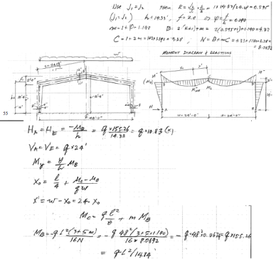
By contrast, senior-level engineers with plenty of experience tend to deal with managerial tasks rather than repetitive computer analysis. Wouldn’t it be great if those who run the software or check the output could quickly verify the results by some approximate hand calculations? Many engineers wish there was a course addressing this very real need, and this is the webinar they have been seeking!

The presentation covers many rules of thumb for designing building elements of various types and materials. It includes simplified formulas for analysis of continuous beams, rigid frames, basic formulas for quickly computing the required beam stiffness, and other practical data to help quickly evaluate computer-generated designs.

Learning Outcomes

Know how to verify computer calculations by approximate methods of analysis for different structural systems

asce-1000-8

  • Become familiar with the rules of thumb for proportioning various types of framing
  • Learn how to quickly find the required beam stiffness for various materials and deflection criteria

Webinar Benefits

  • Find out how to conduct a sanity check of computer-generated designs
  • Discover simple and once-popular methods of computing forces and bending moments in rigid frames
  • Learn how to quickly find the bending moments in continuous beams
  • Explore the shortcuts for controlling deflections in beams of various materials

Intended Audience

Structural and civil engineers, architects, and building officials seeking to find out how to verify computer-generated designs and calculations by approximate methods of analysis will benefit from this webinar.

Webinar Outline

Why computer-generated calculations may need verification
Rules of thumb for proportioning various framing systems
Quick analysis of continuous framing
Checking computer design of rigid frames
Shortcuts for beam design and deflections control

Design Based on Codes

By Howard Velasquez, P.E.,M.ASCE

Design based on Codes article intend to list the Civil / Structural Design Codes involved in making structural engineering products. It is important to stand that Engineers and their practice are conducted by several rules which must be accomplished in order to provide the society safe, reliable and economic infrastructure. It is not a game, it’s a ruled professional practice and should be respected as that.

Civil Engineering cover the following branches:

  • Surveying
  • Construction Engineering
  • Transportation Engineering
  • Fluid Mechanics
  • Irrigation Engineering
  • Structural Engineering
  • Geotechnical Engineering
  • Foundation Engineering
  • Environmental EngineeringQuantity Surveying
  • Earthquake Engineering

It’s important to establish the difference between a Civil Engineer and a Construction Engineer.

A civil engineer, designs, maintains, plans, constructs, and operates infrastructures while taking care of environmental and public health, as well as refining existing buildings that have been neglected. A Construction engineer, on the other hand, deals with the on-site management of infrastructures like airports, buildings, highways, railroads, bridges, utilities, and dams. Such engineers are a unique blend of civil engineers and construction managers.

They both require different set of degrees for different job profiles and engineering careers. In a nutshell we can say that”

All construction engineers (site engineers) are civil engineers but not all civil engineers are site engineers.

In the next lines, we will try to list the necessary Design Codes that your Engineering Office should have for Bridge Design, Steel Design, Lateral Analysis, Concrete Design and Foundation Design. This list is specially useful for civil engineers.

Bridge Design Group

1 Bridge Concrete Girder Prestressed Concrete Girder Design for Bridge Structure Based on AASHTO 17th Edition & ACI 318-11.
2 Bridge Concrete Column Bridge Column Design Based on AASHTO 17th & ACI 318-11
3 Bridge Box Section Bridge Design for Prestressed Concrete Box Section Based on AASHTO 17th Edition & ACI 318-11
4 Concrete Tunnel Concrete Tunnel Design Based on AASHTO-17th & ACI 318-11
5 Double Tee Prestressed Double Tee Design Based on AASHTO 17th Edition & ACI 318-11
6 Concrete Box Culvert Concrete Box Culvert Design Based on AASHTO 17th Edition & ACI 318-11
7 Steel Road Plate Steel Road Plate Design Based on AASHTO 17th Edition & AISC 360-10 using Finite Element Method
8 Flange Tapered Girder Flange Tapered Plate Girder Design Based on AISC Manual 14th Edition (AISC 360-10)
9 Prestressed Concrete Pole/Pile Prestressed Concrete Circular Hollow Pole/Pile Design Based on ACI 318-11 & AASHTO 17th
10 Falsework Design for Steel Girder Bridge Based on NDS 2012 & AASHTO 17th

Steel Design Group

1 Beam Connection Beam Connection Design Based on AISC 360-10
2 Angle Capacity Angle Steel Member Capacity Based on AISC 360-10
3 HSS-WF Capacity Tube, Pipe, or WF Member Capacity Based on AISC 360-10
4 Metal Studs Metal Member Design Based on AISI S100-07/SI-10 (2012 IBC) & ICBO ER-4943P
5 SMRF – CBC Seismic Design for Special Moment Resisting Frames Based on 2013 CBC
6 SCBF-Parallel Seismic Design for Special Concentrically Braced Frames Based on CBC/IBC & AISC 341-10
7 SCBF-Perpendicular Bracing Connection Design, with Perpendicular Gusset, Based on CBC/IBC & AISC 341-10
8 Column Above Beam Connection Design for Column above Beam, Based on AISC Manual & AISC 360-10
9 Beam Gravity Steel Gravity Beam Design Based on AISC Manual 14th Edition (AISC 360-10)
10 WF Beam with Torsion WF Simply Supported Beam Design with Torsional Loading Based on AISC 360-10
11 HSS (Tube, Pipe) Torsion HSS (Tube, Pipe) Member Design with Torsional Loading Based on AISC 360-10
12 Fixed Bolted Joint Fixed Bolted Joint, with Beam Sitting on Top of Column, Based on AISC 358-10 8ES/4ES & FEMA-350
13 Brace Connection Typical Bracing Connection Capacity Based on AISC 360-10
14 BRBF Buckling-Restrained Braced Frames Based on AISC 360-10 & AISC 341-10
15 BSEP – SMF Bolted Seismic Moment Connection Based on AISC 341-10, 358-10, 360-10 & FEMA-350
16 Bolted Moment Connection Bolted Non-Seismic Moment Connection Based on AISC 341-10, 358-10, 360-10 & FEMA-350
17 Channel Capacity Channel Steel Member Capacity Based on AISC 360-10
18 Composite Collector Beam Composite Collector Beam with Seismic Loads Based on 2013 CBC / 2012 IBC
19 Composite Floor Beam Composite Beam Design Based on AISC Manual 9th
20 Composite Floor Beam with Cantilever Composite Beam Design Based on AISC 360-10 / 2012 IBC / 2013 CBC
21 Composite Floor Girder Composite Girder Design Based on AISC 360-10 / 2012 IBC / 2013 CBC
22 Drag Connection Drag Connection Based on AISC 360-10 & AISC 341-10
23 Drag Forces for Brace Frame Drag / Collector Forces for Brace Frame
24 EBF – CBC Seismic Design for Eccentrically Braced Frames Based on 2013 CBC & AISC 341-10
25 EBF – IBC Seismic Design for Eccentrically Braced Frames Based on 2012 IBC & AISC 341-10
26 Enhanced Composite Beam Enhanced Composite Beam Design Based on AISC 360-10 / 2012 IBC / 2013 CBC
27 Enhanced Steel Beam Enhanced Steel Beam Design Based on AISC 14th (AISC 360-10)
28 Exterior Metal Stud Wall Exterior Metal Stud Wall Design Based on AISI S100-07/SI-10 & ER-4943P
29 Floor Deck Depressed Floor Deck Capacity (Non-Composite)
30 Gusset Geometry Gusset Plate Dimensions Generator
31 Metal Shear Wall Metal Shear Wall Design Based on AISI S100-07/SI-10, ER-5762 & ER-4943P
32 Metal Shear Wall Opening Metal Shear Wall with an Opening Based on AISI S100-07/SI-10, ER-5762 & ER-4943P
33 Metal Z Purlins Metal Z-Purlins Design Based on AISI S100-07/SI-10
34 OCBF – CBC Ordinary Concentrically Braced Frames Based on 2013 CBC & AISC 341-10
35 OCBF – IBC Ordinary Concentrically Braced Frames Based on 2012 IBC & AISC 341-10
36 Web-Tapered Cantilever Frame Web-Tapered Cantilever Frame Design Based on AISC-ASD 9th, Appendix F
37 OMRF – CBC Intermediate/Ordinary Moment Resisting Frames Based on 2013 CBC
38 OMRF – IBC Intermediate/Ordinary Moment Resisting Frames Based on 2012 IBC
39 Plate Girder Plate Girder Design Based on AISC Manual 14th Edition (AISC 360-10)
40 Rectangular Section Rectangular Section Member Design Based on AISC 360-10
41 Roof Deck Design of 1 1/2″ Type “B” Roof Deck Based on ICBO ER-2078P
42 Base Plate Base Plate Design Based on AISC Manual 14th Edition (AISC 360-10)
43 SMRF – IBC Special Moment Resisting Frames Based on 2012 IBC, AISC 341-10 & 358-10
44 SPSW Seismic Design for Special Plate Shear Wall Based on AISC 341-10 & AISC 360-10
45 Steel Column Steel Column Design Based on AISC Manual 14th Edition (AISC 360-10)
46 Steel Stair Steel Stair Design Based on AISC 360-10
47 Triple W Shapes Simply Supported Member of Triple W-Shapes Design Based on AISC 360-10
48 Portal Frame Portal Frame Analysis using Finite Element Method
49 Web Tapered Frame Web Tapered Frame Design Based on AISC-ASD 9th Appendix F and/or AISC Design Guide 25
50 Web Tapered Girder Web Tapered Girder Design Based on AISC-ASD 9th Appendix F and/or AISC Design Guide 25
51 Weld Connection Weld Connection Design Based on AISC 360-10
52 WF Opening Check Capacity of WF Beam at Opening Based on AISC 360-10
53 Moment across Girder Design for Fully Restrained Moment Connection across Girder Based on AISC 360-10
54 Beam Bolted Splice Beam Bolted Splice Design Based on AISC Manual 14th Edition (AISC 360-10)
55 Filled Composite Column Filled Composite Column Design Based on AISC 360-10 & ACI 318-11
56 Cellular Beam Cellular Beam Design Based on AISC 360-10
57 Double Angle Capacity Double Angle Capacity Based on AISC 360-10
58 T-Shape Capacity T-Shape Member Capacity Based on AISC 360-10
59 Cantilever Column Cantilever Column & Footing Design Based on AISC 360-10, ACI 318-11, and IBC 1807.3
60 Metal Truss Light Gage Truss Design Based on AISI S100-07/SI-10 & ER-4943P
61 Sleeve Joint Connection Sleeve Joint Connection Design, for Steel Cell Tower / Sign, Based on AISC 360-10
62 Moment to Column Web Moment Connection Design for Beam to Weak Axis Column Based on AISC 360-10

Lateral Analysis Group

1 Seismic vs Wind Three, Two, and One Story Comparison of Seismic and Wind Based on 2012 IBC / 2013 CBC
2 Wind – ASCE7-10 Wind Analysis Based on ASCE 7-10
3 Seismic – 2012 IBC Seismic Analysis Based on ASCE 7-10
4 Metal Pipe/Riser MCE Level Seismic Design for Metal Pipe/Riser Based on ASCE 7-10 & AISI S100
5 Rigid Diaphragm Rotation Analysis of Rigid Diaphragm Based on 2012 IBC / 2013 CBC
6 Flexible Diaphragm Flexible Diaphragm Analysis
7 Two Story Moment Frame Two Story Moment Frame Analysis using Finite Element Method
8 X – Braced Frame X-Braced Frame Analysis using Finite Element Method
9 Open Structure Wind Wind Analysis for Open Structure (Solar Panels) Based on ASCE 7-10 & 05
10 Roof Screen/Equipment Wind Wind Load, on Roof Screen / Roof Equipment, Based on ASCE 7-10 & 05
11 Axial Roof Deck Axial Capacity of 1 1/2″ Type “B” Roof Deck Based on ICBO ER-2078P
12 Deformation Compatibility Column Deformation Compatibility Design using Finite Element Method
13 Discontinuous Shear Wall Discontinuous Shear Wall Analysis Using Finite Element Method
14 Flexible Diaphragm Opening Flexible Diaphragm with an Opening Analysis
15 Hand Rail Handrail Design Based on AISC 360-10 & ACI 318-11
16 Interior Wall Lateral Force Interior Wall Lateral Forces Based on 2012 IBC / 2013 CBC
17 Lateral Frame Formulas Lateral Frame Formulas
18 Live Load Live Load Reduction Based on ASCE 7-10, 2012 IBC / 2013 CBC
19 Seismic – Single Family Dwellings Seismic Analysis for Family Dwellings Based on 2012 IBC / 2013 CBC
20 Shade Structure Wind Wind Analysis for Shade Open Structure Based on ASCE 7-10 & 05
21 Shear Wall Forces Shear Wall Analysis for Shear Wall with Opening Using Finite Element Method
22 Shear Wall – New Opening Relative Rigidity Determination for Shear Wall with New Opening
23 Shear Wall Rigidity Rigidity for Shear Wall & Shear Wall with Opening Using Finite Element Method
24 Sign Sign Design Based on AISC 360-10, ACI 318-11, and IBC 1807.3
25 Sign Wind Wind Analysis for Freestanding Wall & Sign Based on ASCE 7-10 & 05
26 Snow Snow Load Analysis Based on ASCE 7-10, 05, & UBC
27 Wall Lateral Force – CBC Lateral Force for One-Story Wall Based on 2013 CBC
28 Wall Lateral Force – IBC Lateral Force for One-Story Wall Based on 2012 IBC
29 Seismic – 2009 IBC Seismic Analysis Based on 2009 IBC / 2013 CBC
30 Wind Girt Deflection Wind Girt Deflection Analysis of Wood, Metal Stud, and/or Steel Tube
31 Storage Racks Lateral Loads of Storage Racks, with Hilti & Red Head Anchorage, Based on ASCE 7-10
32 Wind Alternate Method Wind Analysis for Alternate All-Heights Method, Based on ASCE 7-10
33 Ceiling Seismic Loads Suspended Ceiling Seismic Loads Based on ASCE 7-10
34 Response Spectrum Generator Earthquake Response Spectrum Generator
35 Tornado and Hurricane Wind Analysis for Tornado and Hurricane Based on 2012 IBC Section 423 & FEMA 361/320
36 Stiffness Matrix Generator Stiffness Matrix Generator for Irregular Beam/Column
37 PT-Column Drift Lateral Drift Mitigation for Cantilever Column using Post-Tensioning
38 Blast Mitigation Blast Deformation Mitigation for Gravity Column using Post-Tensioning
39 Wind – SEAOC-PV2 Wind Design for Low-Profile Solar Photovoltaic Arrays on Flat Roof, Based on SEAOC PV2-2012
40 Wind – ASCE7-05 Wind Analysis Based on ASCE 7-05, Including Roof Solar Panel Loads

Concrete Design Group

1 Two Way Slab Two-Way Slab Design Based on ACI 318-11 using Finite Element Method
2 Voided Biaxial Slab Voided Two-Way Slab Design Based on ACI 318-11
3 Anchorage to Concrete Base Plate and Group Anchors Design Based on ACI 318-11 & AISC 360-10
4 Anchorage to Pedestal Anchorage to Pedestal Design Based on ACI 318-11 & AISC 360-10
5 Circular Column Circular Column Design Based on ACI 318-11
6 Concrete Column Concrete Column Design Based on ACI 318-11
7 Super Composite Column Super Composite Column Design Based on AISC 360-10 & ACI 318-11
8 Special Shear Wall – CBC Special Concrete Shear Wall Design Based on ACI 318-11 & 2013 CBC Chapter A
9 Ordinary Shear Wall Ordinary Concrete Shear Wall Design Based on ACI 318-11
10 Concrete Pool Concrete Pool Design Based on ACI 318-11
11 Corbel Corbel Design Based on 2012 IBC / ACI 318-11
12 Coupling Beam Coupling Beam Design Based on ACI 318-11
13 Deep Beam Deep Beam Design Based on ACI 318-11
14 Concrete Development & Splice Development & Splice of Reinforcement Based on ACI 318-11
15 Equipment Mounting Design for Equipment Anchorage Based on 2012 IBC & 2013 CBC Chapter A
16 Existing Shear Wall Verify Existing Concrete Shear Wall Based on ASCE 41-06 / 2013 CBC / 2012 IBC
17 Friction Shear Friction Reinforcing Design Based on ACI 318-11
18 Pipe Concrete Column Pipe Concrete Column Design Based on ACI 318-11
19 PT-Concrete Floor Design of Post-Tensioned Concrete Floor Based on ACI 318-11
20 Punching Slab Punching Design Based on ACI 318-11
21 Concrete Slab Concrete Slab Perpendicular Flexure & Shear Capacity Based on ACI 318-11
22 Voided Section Capacity Voided Section Design Based on ACI 318-11
23 Concrete Diaphragm Concrete Diaphragm in-plane Shear Design Based on ACI 318-11
24 SMRF – ACI Seismic Design for Special Moment Resisting Frame Based on ACI 318-11
25 Special Shear Wall – IBC Special Reinforced Concrete Shear Wall Design Based on ACI 318-11 & 2012 IBC
Technical Support
Purchaser will receive, by USB flash drive, the purchased XLSB/XLS version software within 4 days (network version can be downloaded on the purchased day). For package purchaser, please email us your left top
logo with your order. Any our software bugs can be fixed promptly, and the updated software will be emailed back to reporter.
Custom Software & Analysis
If our Package still cannot cover your design, please email us to know. We provide custom spreadsheet & analysis service for Package purchaser.
Full Structural Consultanting Service
For Nonlinear Structural Analysis , Performance-Based Seismic Design , and quality structural consultanting service, please contact DJ Engineers & Builders Inc.
26 Suspended Anchorage Suspended Anchorage to Concrete Based on 2012 IBC & 2013 CBC
27 Tiltup Panel Tilt-up Panel Design based on ACI 318-11
28 Wall Pier Wall Pier Design Based on 2013 CBC & 2012 IBC
29 Beam Penetration Design for Concrete Beam with Penetration Based on ACI 318-11
30 Column Supporting Discontinuous Column Supporting Discontinuous System Based on ACI 318-11
31 Plate Shell Element Plate/Shell Element Design Based on ACI 318-11
32 Transfer Diaphragm – Concrete Concrete Diaphragm Design for a Discontinuity of Type 4 out-of-plane offset irregularity
33 Silo/Chimney/Tower Design Concrete Silo / Chimney / Tower Design Based on ASCE 7-10, ACI 318-11 & ACI 313-97
34 Concrete Beam Concrete Beam Design, for New or Existing, Based on ACI 318-11

Foundation Design Group

1 Free Standing Wall Free Standing Masonry & Conctere Wall Design Based on TMS 402-11 & ACI 318-11
2 Eccentric Footing Eccentric Footing Design Based on ACI 318-11
3 Flagpole Flagpole Footing Design Based on 2012 IBC Chapter 18
4 Masonry Retaining Wall Masonry Retaining / Fence Wall Design Based on TMS 402-11 & ACI 318-11
5 Concrete Retaining Wall Concrete Retaining Wall Design Based on ACI 318-11
6 Masonry-Concrete Retaining Wall Retaining Wall Design, for Masonry Top & Concrete Bottom, Based on TMS 402-11 & ACI 318-11
7 Concrete Pier Concrete Pier (Isolated Deep Foundation) Design Based on ACI 318-11
8 Concrete Pile Drilled Cast-in-place Pile Design Based on ACI 318-11
9 Pile Caps Pile Cap Design for 4, 3, 2-Piles Pattern Based on ACI 318-11
10 Pile Cap Balanced Loads Determination of Pile Cap Balanced Loads and Reactions
11 Conventional Slab on Grade Design of Conventional Slabs on Expansive & Compressible Soil Grade Based on ACI 360
12 PT-Slab on Ground Design of PT Slabs on Expansive & Compressible Soil Based on PTI 3rd Edition
13 Basement Concrete Wall Basement Concrete Wall Design Based on ACI 318-11
14 Basement Masonry Wall Basement Masonry Wall Design Based on TMS 402-11
15 Basement Column Basement Column Supporting Lateral Resisting Frame Based on ACI 318-11
16 MRF-Grade Beam Grade Beam Design for Moment Resisting Frame Based on ACI 318-11
17 Brace Grade Beam Grade Beam Design for Brace Frame Based on ACI 318-11
18 Grade Beam Two Pads with Grade Beam Design Based on ACI 318-11 & AISC 360-10
19 Circular Footing Circular Footing Design Based on ACI 318-11
20 Combined Footing Combined Footing Design Based on ACI 318-11
21 Boundary Spring Generator Mat Boundary Spring Generator
22 Deep Footing Deep Footing Design Based on ACI 318-11
23 Footing at Piping Design of Footing at Piping Based on ACI 318-11
24 Irregular Footing Soil Pressure Soil Pressure Determination for Irregular Footing
25 PAD Footing Pad Footing Design Based on ACI 318-11
26 Plain Concrete Footing Plain Concrete Footing Design Based on ACI 318-11
27 Restrained Retaining Wall Restrained Retaining Masonry & Concrete Wall Design Based on TMS 402 & ACI 318
28 Retaining Wall for DSA /OSHPD Retaining Wall Design Based on 2013 CBC Chapter A
29 Tank Footing Tank Footing Design Based on ACI 318-11
30 Temporary Footing for Rectangular Tank Temporary Tank Footing Design Based on ACI 318-11
31 Under Ground Well Under Ground Well Design Based on ACI 350-06 & ACI 318-11
32 Stud Bearing Wall Footing Footing Design for Stud Bearing Wall Based on 2012 IBC / ACI 318-11
33 Wall Footing Footing Design of Shear Wall Based on ACI 318-11
34 Fixed Moment Condition Fixed Moment Condition Design Based on ACI 318-11
35 Flood Way Concrete Floodway Design Based on ACI 350-06 & ACI 318-11
36 Lateral Earth Pressure Lateral Earth Pressure of Rigid Wall Based on AASHTO 17th & 2012 IBC
37 Shoring Sheet Pile Wall Design Based on 2012 IBC / 2013 CBC / ACI 318-11

The list above has been copied from “DJ Engineers & Builders Inc.” web page.

The Seven Fundamental Canons of ASCE’s Code of Ethics

asce-1

1. Engineers shall hold paramount the safety, health, and welfare of the public and shall strive to comply with the principles of sustainable development in the performance of their professional duties. 

Perhaps the most demanding of ASCE’s ethical standards is the engineer’s duty to “hold paramount” the public’s safety and welfare. Under this canon an engineer is expected not only to protect the public in his or her own work but also to take action if he or she has knowledge that any other person’s actions may undermine the public welfare, a requirement that may include reporting such actions to a government authority with the power to act on behalf of the public. In 1996 ASCE added the “sustainable development” language to this canon, reflecting its belief that ensuring public welfare also requires consideration of ecological and environmental factors.

2. Engineers shall perform services only in areas of their competence. 

In addition to the more obvious guidelines here, for example, the requirement to take work only when qualified by education or experience to carry out the work, this canon means that an engineer may not seal an engineering plan or document unless that document has been prepared or reviewed under his or her supervisory control. As discussed in this column in the August 2007 issue, this provision is considerably less restrictive than the licensing laws in many U.S. states and jurisdictions, underlining the need for civil engineers to be aware of state codes of conduct as well as those of ASCE.

3. Engineers shall issue public statements only in an objective and truthful manner. 

This canon considers the many ways in which an engineer may share his or her expertise with the public and reflects principles that underlie many other provisions of the code. For example, an engineer may apply his or her technical expertise only when competent to do so (as per canon 2), must indicate when a statement has been paid for by an interested party (much like the conflict disclosures required by canon 4), and may not promote his or her own interests in a manner derogatory to the integrity of the profession (canon 6).

4. Engineers shall act in professional matters for each employer or client as faithful agents or trustees, and shall avoid conflicts of interest. 

With its focus on fidelity to employers and clients, canon 4 is in some respects reminiscent of the original, 1914 code. But whereas that code barred an engineer only from “accept[ing] remuneration other than his stated charges for services rendered,” the current canon provides a more complete picture of the types of conflicts that can lead an engineer astray. Under today’s canon, engineers may not use confidential information in a way that is detrimental to an employer’s or client’s interests, may not take part in decisions as a public servant for services involving their own private practice, and are obliged to notify their employers before availing themselves of outside employment opportunities or engaging in work that may give rise to a conflict of interest.

5. Engineers shall build their professional reputation on the merit of their services and shall not compete unfairly with others.

An important point to remember here is that this canon does not restrict competition among engineers per se, only methods by which an engineer may attempt to gain an unfair advantage over his or her competitors. Such unfair practices include bestowing gifts or gratuities to obtain work, falsely portraying one’s qualifications and credentials, taking credit for the work of another, and maliciously criticizing the work of another.

6. Engineers shall act in such a manner as to uphold and enhance the honor, integrity, and dignity of the engineering profession and shall act with zero tolerance for bribery, fraud, and corruption.

This canon can be viewed as a catchall for acts that while not expressly proscribed in other canons nevertheless violate the spirit of the code. It promotes transparency and scrupulous control of funds and prohibits engineers from knowingly participating in fraudulent or dishonest practices. This canon also reflects the most recent revision to the code, a 2006 amendment stating that bribes and corruption are not to be tolerated and warning engineers to beware of situations where such practices have broad, even institutionalized, support.

7. Engineers shall continue their professional development throughout their careers, and shall provide opportunities for the professional development of those engineers under their supervision.

The final canon is unique in that its focus is on professional growth rather than professional conduct. Engineers are encouraged to continue honing their skills, to share their knowledge by, for example, attending conferences and seminars, and to support the development of engineer employees by providing them with an environment that encourages professional growth and licensure.

For readers interested in a more thorough study of ASCE’s Code of Ethics, the complete text of the most current version is published each year in the Official Register. That work may be accessed online by clicking on “Official Register” in the “Inside ASCE” menu at www.asce.org . Alternatively, the Code of Ethics may be accessed separately by selecting “Ethics” in the “Professional Issues” menu at www.asce.org .